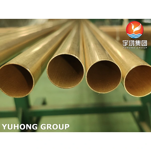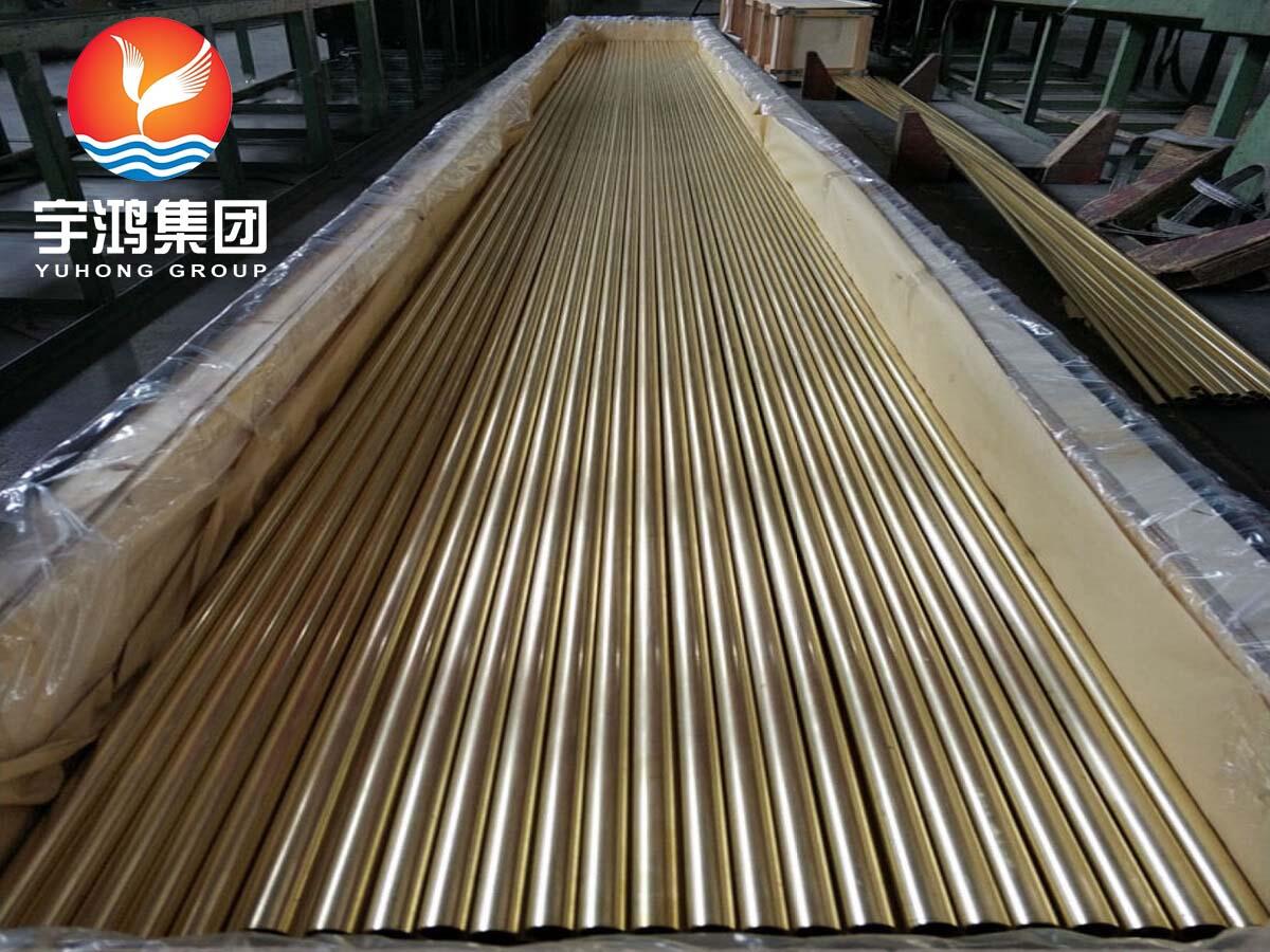
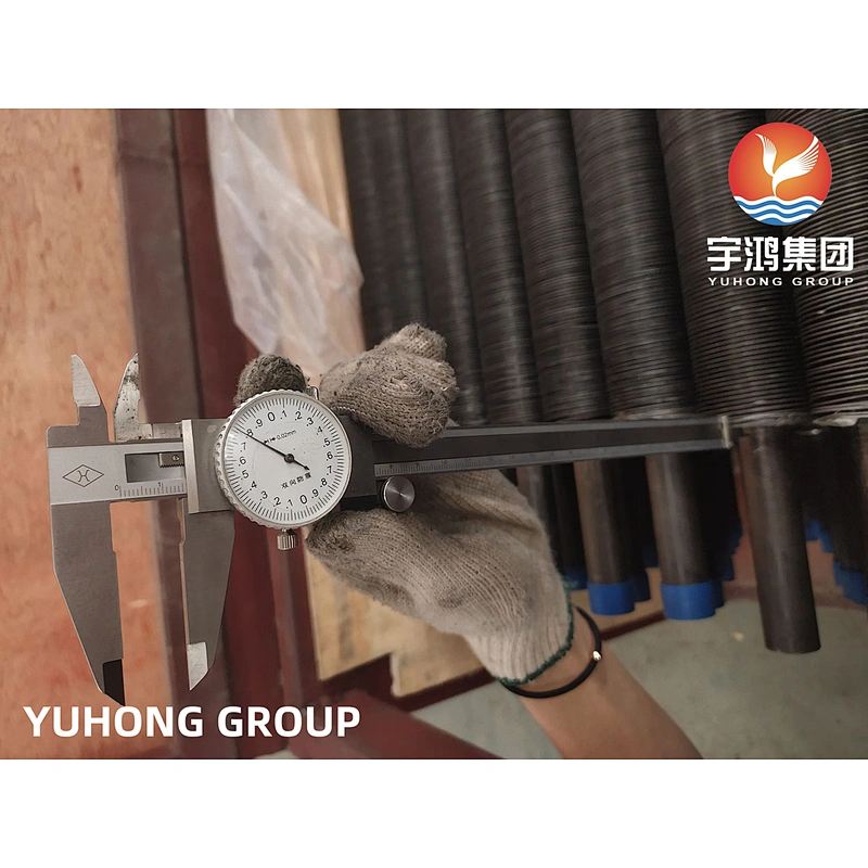


ASTM A179 covers minimum-wall thickness, seamless cold-drawn low-carbon steel tubes for tubular, heat exchanger, condensers, and other heat transfer services. seamless ASTM A 179 steel tube is supplied and produced by cold drawning method. Chemical composition contains carbon, manganese, phosphorus, and sulfur.
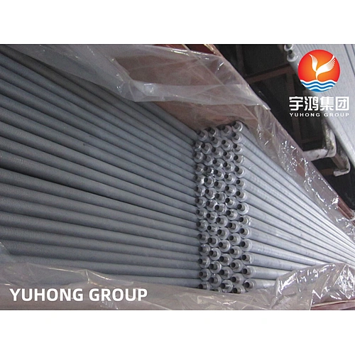
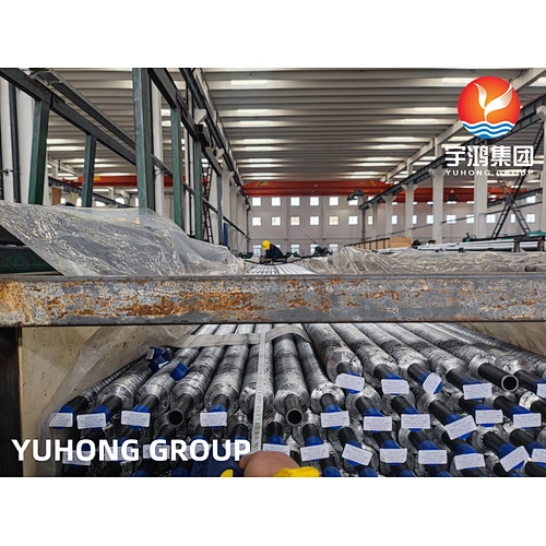
SA179 steel tube contains the accompanying determinations: ASTM A179/ASME SA179 with Seamless – Hot Rolled or Cold Drawn sort, 1/4"NB To 2"NB (Nominal Bore Size) external Diameter, 1 mm Thickness to 8 mm divider Thickness, length as 5800mm/ 6000mm/ 6096mm/ 7315mm/ 11800mm, etc upto Max length 27000mm with Plain Ends/Beveled Ends/Coupling. Measures A179 Tube Seamless Cold-Drawn Low-Carbon Steel Heat-Exchanger and Condenser Tubes, Tube Certified and Tested as per Impact Test, Heat Treated, Hardness Test, Flattening Test, Reverse Flattening Test, Flaring Test, Flange Test, Hydrostatic Test. The Carbon Steel A179 Heat-Exchanger Tube is carefully exposed to different tests so as to guarantee the nature of the item. This evaluation of the cylinder is stuffed in wooden box or case so as to maintain a strategic distance from outer harm amid the last phase of creation. These evaluations of cylinders are utilized in different modern applications and are accessible in market driving costs. You can without much of a stretch purchase this cylinder from our market sellers.
ASTM A179 TUBES SPECIFICATIONS
| Standards | ASTM, ASME and API |
| Size | 1/2” NB to 36” NB |
| Thickness | 3-12mm |
| Schedules | SCH 40, SCH 80, SCH 160, SCH XS, SCH XXS, All Schedules |
| Tolerance | Cold drawn pipe: +/-0.1mm Cold rolled pipe: +/-0.05mm |
| Craft | Cold rolled and Cold drawn |
| Type | Seamless / ERW / Welded / Fabricated |
| Form | Round Pipes/Tubes, Square Pipes/Tubes, Rectangular Pipe/Tubes, Coiled Tubes, “U” Shape, Pan Cake Coils, Hydraulic Tubes |
| Length | Min 3 Meters, Max18 Meters, or according to customer’s requirement |
| End | Plain End, Beveled End, Treaded |
Chemical Composition (%) Max.
C | Mn | P≤ | S≤ | Si≤ |
0.06-0.18 | 0.27-0.63 | 0.035 | 0.035 | 0.25 |
Mechanical Properties
Tensile Strength(Mpa) | Yield Strength(Mpa) | Elongation(%) | Hardness(HRB) |
325 Min | 180 Min | 35 Min | 72 max |
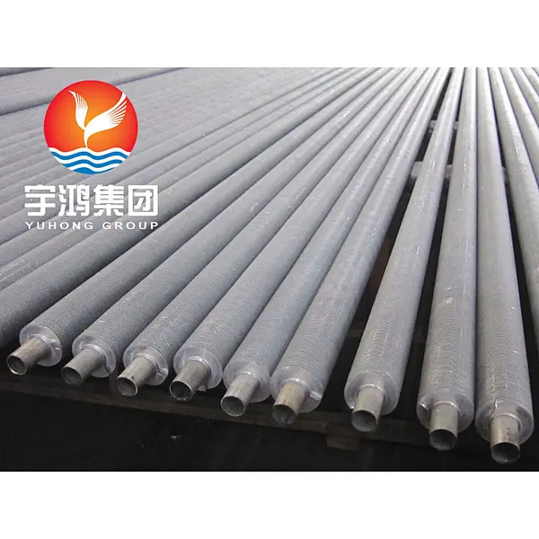
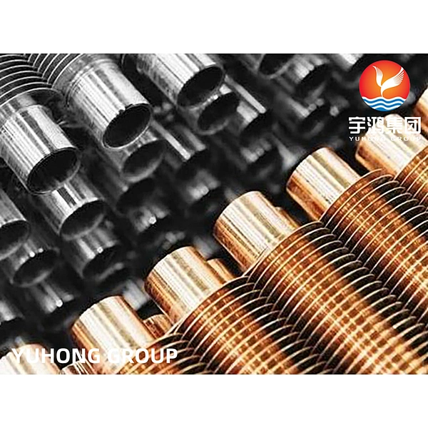
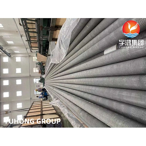
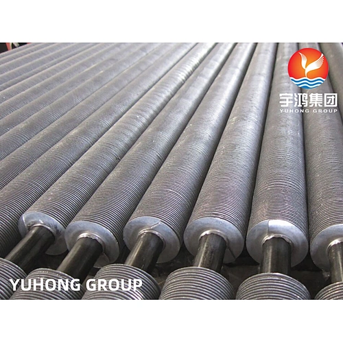
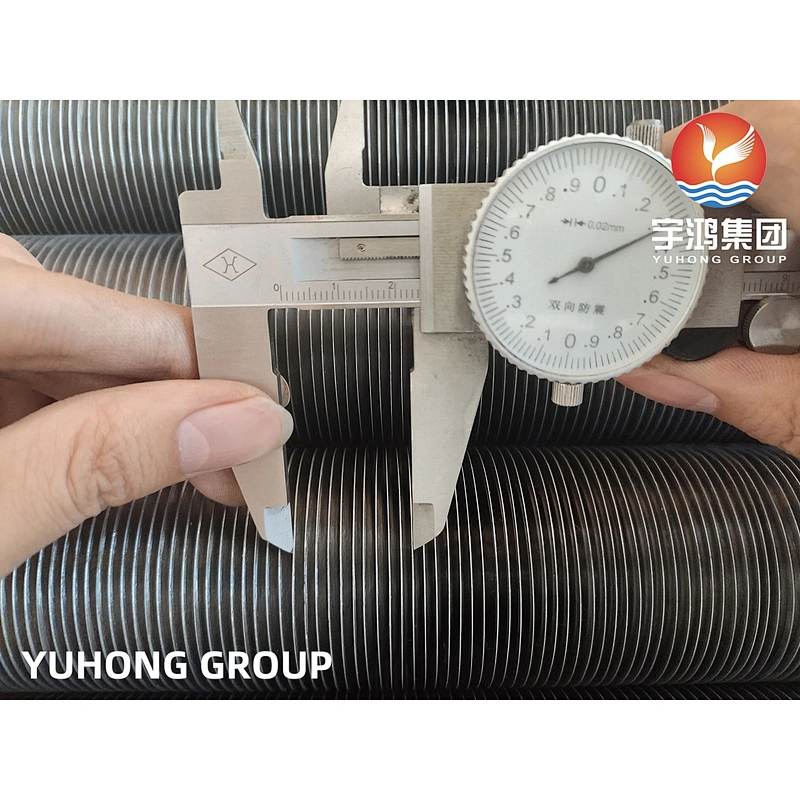
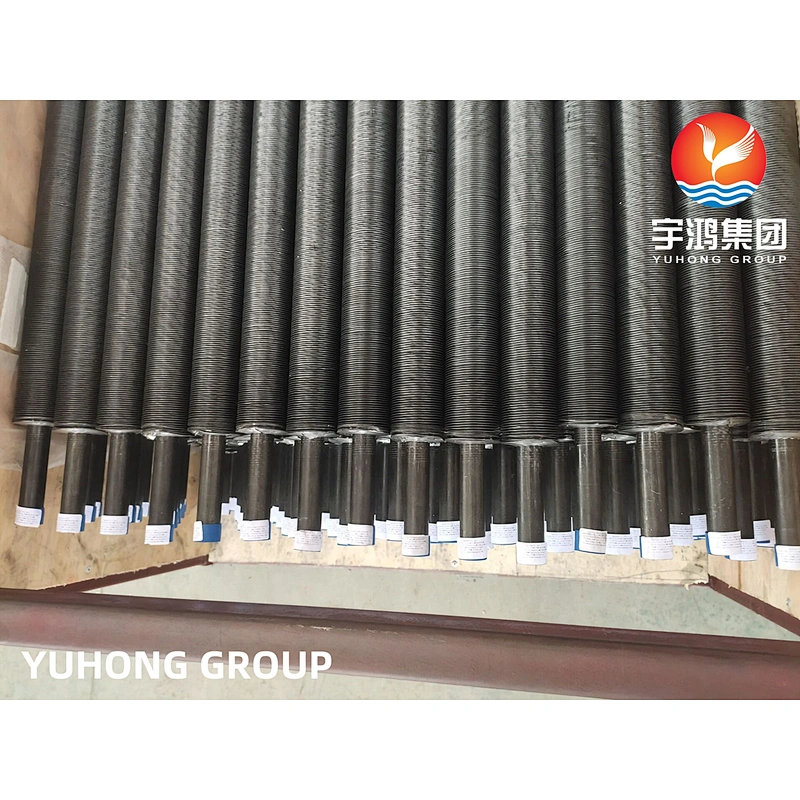
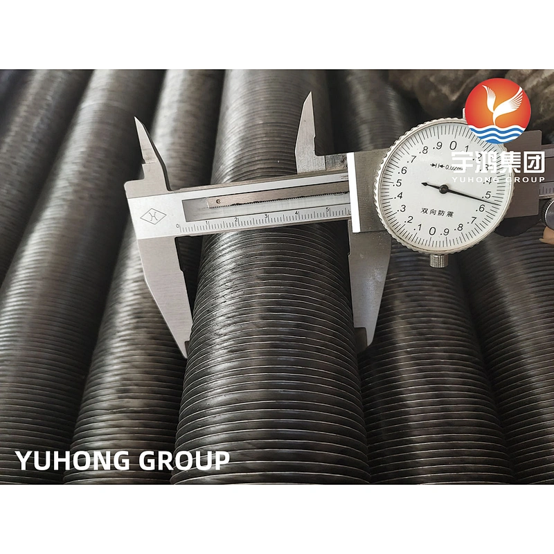
The G FIN TUBE is also known as Embedded Fin Tube. This type of fin tube widely finds acceptance where the requirement is for higher operating temperature and relatively lower corrosive atmosphere. The fins are manufactured by embedding the fin strip into a groove formed on the base tube. The Fin is allowed to be placed in the groove and then the backfilling of the groove is carried out to ensure firm adherence of the fins to the base tubes. Because of the process this type of Fin Tube is also known as G Fin tube or Grooved Fin Tube.
The grooving, fin stack inserting and the backfilling processes are carried put simultaneously as continuous operation. Because of the back filling procedure the bond between the Fin material and the Base tube is one of the best. This ensures optimum Heat Transfer. These Fin Tubes find application in AIR FIN COOLERS, RADIATORS etc. and are preferred in Industries like Power Plants, Chemical Industries, Petroleum Refineries, Chemical process Plants, Rubber Plants, etc.
G Type Fin Tube| Embedded Finned Tube
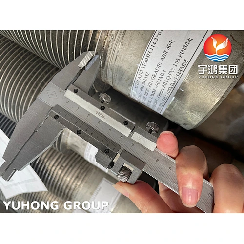
G Fin Tube discription: The fin strip is wound into a mechanically produced groove and tightened by backfilling of the base material under pressure.
Groove depth appr: 0.4 mm.
Advantages: High fin stability, excellent heat transfer, high operating temperature.
G Type Fin Tube Material Combinations
G Fin Tube Core Tube: Carbon steels, low-alloy steels, stainless steels, brass,copper, copper-nickel alloys, aluminium bronze, nickel-alloys (Alloy 400, etc.), bimetal, titanium and others
G Fin Tube Fins: Aluminium / Copper / Steel / Galvanized Steel
G Type Fin Tube Fields of Application
• The petroleum, chemical and petrochemical industries
• Natural gas treatment
• The steel industry: blast furnace and converter systems
• Power generation: steam turbine exhaust condensing
– Contact condensing with cooling of circulating condensate
– Fossil and nuclear power plants
• Air conditioning (freon, ammonia, propane)
• Incineration of household refuse
• Compressor coolers, ect.
G Type Fin Tube Manufacturing Process
The manufacturing tool is made up of 2 non-cutting plates set at 90° to the axis of the base tube. The first plate effects a groove for metal spinning. The second directs the ribbon in the groove and sets the fin foot in the groove through pressure on the metal displaced for the groove. A similar plate made of tungsten carbure allows us to manufacture G finned tubes with base tubes made of austenitic steel or exotic alloys.
G Type Fin Tube Advantages
1) G Fin Tube Thermal. The fin/tube wall contact is constant because of the setting and makes it possible to use a wall temperature of up to 400° C.
2) G Fin Tube Mechanical. The fin is set throughout its length and consequently does not unwind even when partially uprooted.
Features
1. Dimensional accuracy.
2. High strength
3. Durable
4. Corrosion resistance
5. Fine finish
Application
1. Pharmaceutical Equipment
2. Chemical Equipment
3. Sea Water Equipment
4. Heat Exchangers
5. Condensers
6. Pulp and Paper Industry
7. Off-Shore Oil Drilling Companies
8. Power Generation
9. Petrochemicals
10. Gas Processing
11. Specialty Chemicals
12. Pharmaceuticals