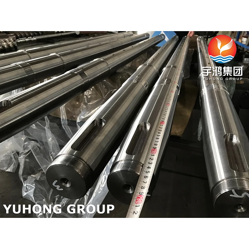
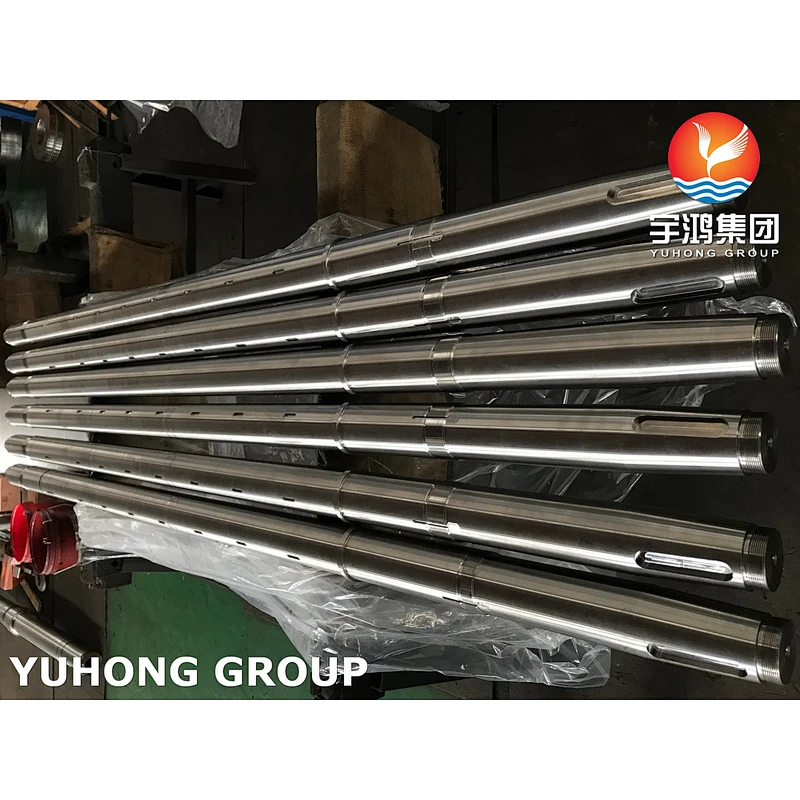
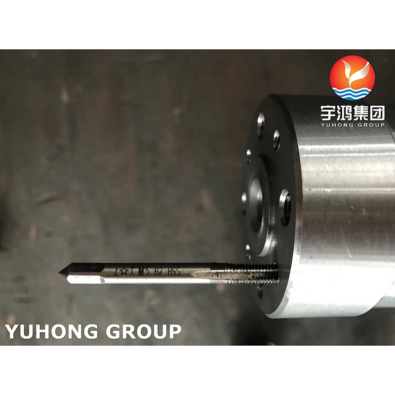
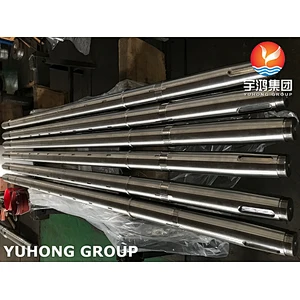
What Kind of Shaft There Is
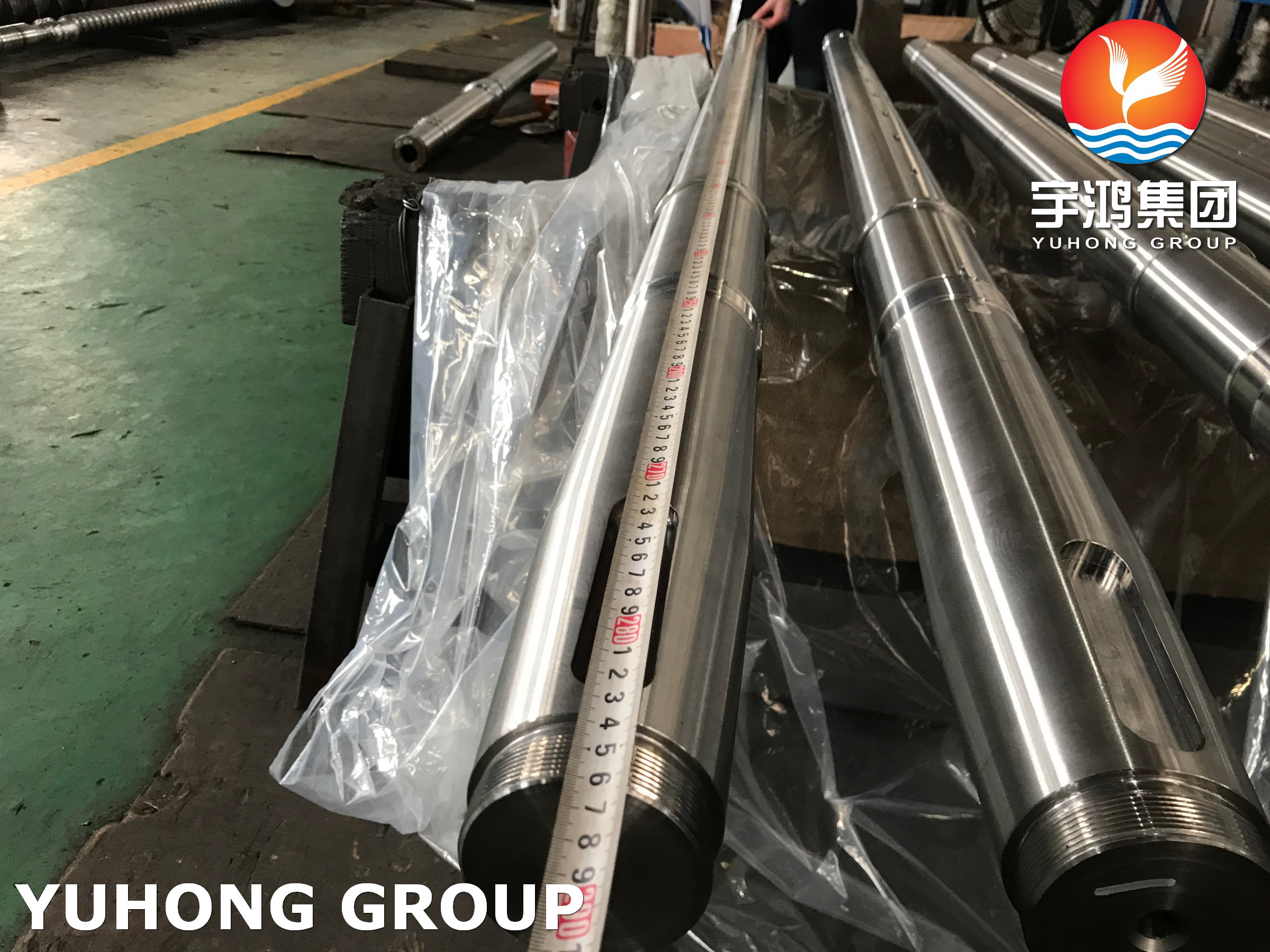
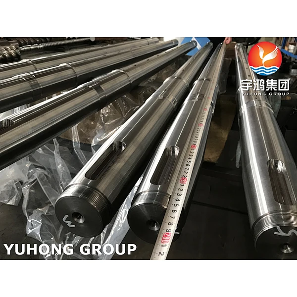
A shaft is a cylindrical object worn in the middle of a bearing or in the middle of a wheel or gear, but also, to a lesser extent, in the middle of a square. A shaft is a mechanical component that supports and rotates with a rotating part in order to transmit motion, torque or bending moment. It is generally in the form of a round metal rod, and the segments can have different diameters. The parts of the machine that move in a rotary motion are mounted on the shaft.
Classification of shafts
Common shafts can be divided into crankshafts, straight shafts, flexible shafts, solid shafts, hollow shafts, rigid shafts and flexible shafts (soft shafts) according to the structural shape of the shaft. Straight shafts can be further divided into:
① Rotating shafts, which work with both bending moment and torque, are the most common shafts in machinery, such as the shafts in various reducers, etc.
② mandrel, used to support the rotating parts only to bear the bending moment and not to transmit torque, some mandrel rotation, such as the axle of railway vehicles, etc., some mandrel is not rotating, such as supporting the shaft of the pulley, etc.
③ Drive shaft, mainly used to transmit torque and not bear the bending moment, such as the long light shaft in the crane moving mechanism, the drive shaft of the car, etc. The material of the shaft is mainly carbon steel or alloy steel, but also ductile iron or alloy cast iron, etc. The working capacity of a shaft generally depends on strength and stiffness and, at high speeds, on vibration stability.
Couplings
( Often shafts cannot run alone and couplings are necessary to enable them to run properly )
Couplings belong to the category of general purpose mechanical parts and are used to connect two shafts (active and driven) in different bodies to rotate together to transmit torque. In high-speed, heavy-duty power transmission, some couplings also cushion, damping and improve the dynamic performance of the shaft system. The coupling is made up of two halves, which are connected to the main shaft and the driven shaft. Commonly used couplings are diaphragm couplings, drum tooth couplings, universal couplings, safety couplings, flexible couplings and serpentine spring couplings.
Selection of materials
The decision is mainly based on the strength, stiffness and wear resistance of the shaft as well as the manufacturing process, with the aim of being economical and reasonable. For larger forces, axial size, weight restrictions or some special requirements can be used alloy steel. Such as 40Cr alloy steel can be used for medium precision, high speed work occasions, the material has a good comprehensive mechanical properties after tempering; choose Cr15, 65Mn and other alloy steel can be used for higher precision, poor working conditions, these materials after tempering and surface quenching of its wear resistance, fatigue strength properties are better.
What Is a Shaft
A shaft is a rotating machine element, usually circular in cross section, which is used to transmit power from one part to another, or from a machine which produces power to a machine that absorbs power. Shaft form the important element of machines. They support rotating parts like gears and pulleys and are themselves supported by bearings resting in the rigid machine housing.
Shaft Design
1. Design of Shaft on the Basis of Strength
Transmission shafts are usually liable to bending moment, torsional moment, axial tensile force and their combinations. Generally shafts are subjected to combined loading of torsional stresses and bending stresses.
- Shaft subjected to tensile stress
Tensile stress = P/ A
Where, A = (π/ 4) x D²
D is Diameter of the shaft in mm
- Shaft subjected to the bending moment
Bending stress = (Mb x Y)/ I
Where,
Mb = Bending Moment
Y = D/ 2 in which D is diameter
I = Moment of inertia = (π x D⁴)/ 64
- Shaft subjected to the torsional moment
Torsional stress = Mt x R/ J
Where,
Mt = torsional moment
R = D/ 2 in which D is the diameter
J = Polar moment of inertia = (π x D⁴)/ 32
2. Design of Shaft on the Basis of Rigidity Basis
Transmission shaft are known as rigid on torsional rigidity basis if the shaft does not twist too much.
{Mt/ J} = {(G x ө)/ L}
Where,
Mt = Torsional moment in N – mm
J = Polar moment of inertia = (π x D⁴)/ 32
D = Diameter of shaft in mm
Ө = Angle of twist
G = Modulus of rigidity in N/ mm²
Chemical Composition
Grade | C | Mn | Si | P | S | Cr | Ni | |
431 | min. max. | - 0.20 | - 1 | - 1 | - 0.04 | - 0.03 | 15 17 | 1.25 2.50 |
Mechanical Properties
Tempering Temperature (°C) | Tensile Strength (MPa) | Yield Strength 0.2% Proof (MPa) | Elongation (% in 50mm) | Hardness Brinell (HB) | Impact Charpy V (J) |
Annealed * | 862 | 655 | 20 | 285 max | - |
204 | 1345 | 1055 | 20 | 388 | 50 |
316 | 1295 | 1035 | 19 | 375 | 53 |
427 | 1350 | 1080 | 19 | 388 | # |
538 | 1140 | 965 | 19 | 321 | # |
593 | 1015 | 770 | 20 | 293 | 64 |
650 | 960 | 695 | 20 | 277 | 84 |
Physical Properties
Grade | Density (kg/m3) | Elastic Modulus (GPa) | Mean Coefficient of Thermal Expansion (μm/m/°C) | Thermal Conductivity (W/m.K) | Specific Heat | Electrical Resistivity (nΩ.m) | |||
0-100°C | 0-315°C | 0-538°C | at 100°C | at 500°C | |||||
431 | 7800 | 200 | 10.2 | 12.1 | - | 20.2 | - | 460 | 720 |
Grade Specification Comparison
Grade | UNS No | Old British | Euronorm | Swedish SS | Japanese JIS | ||
BS | En | No | Name | ||||
431 | S43100 | 431S29 | 57 | 1.4057 | X17CrNi16-2 | 2321 | SUS 431 |
Application of Shaft
1. The shaft can be used as a part of rotary constructions such as turbines, fans, and compressors.
2. Be used in reciprocating engines to transmit power from the engine to the driven element.
3. Be used to make machines such as pumps, conveyors, and mills.